Case study
Fast tracking the replacement of Canada’s Champlain Bridge
Montreal, Canada

Client
Government of Canada
Project duration
16 June 2015 - 24 June 2019
Montreal’s Samuel De Champlain Bridge is one of North America’s busiest crossings and a crucial corridor for Canada’s economy. The new 3.4-kilometer-long bridge replaced the previous 57-year-old one, which had become functionally obsolete.
Life cycle
Planning, feasibility, conceptual design
Design
Construction
Operations and maintenance
Decommissioning
Show full process
In 2015 the Government of Canada appointed a joint venture consortium with T.Y. Lin International as the lead designer, to deliver a new bridge within 42 months. The already tight timeline had a short construction window due to environmental and weather factors.
As the lead geotechnical engineer on the project, Fugro developed an approach aimed at minimising uncertainty of ground conditions and optimising the length of deep foundations, to ensure the client’s very tight schedule could be met. We applied our extensive expertise in long-span bridge construction for three main tasks.
“The project received an Honour Award from the California Chapter of the American Council of Engineering Companies (ACEC) in 2020.”
1. Site investigation
We designed a site investigation programme to identify the degree of resistance of the rock at each foundation location by performing 96 borings; downhole geophysics, rock dilatometer tests; cone penetration tests (CPTs) and extensive laboratory testing.
We used our detailed understanding of the layers of soil and rock (Figure 1) when creating the construction plans. Since there were no unexpected issues during construction, the contractor was able to stay on track with the schedule.

Figure 1 - Interpreted Geological Cross Section
2. Geotechnical design recommendations
One of our biggest technical challenges involved designing a foundation for the main span tower that would support heavy weights. Drawing upon our three decades of expertise in foundation design and extensive database of drilled shaft foundation tests-to-failure, we successfully met the tight deadline.
The soft soils right below the protective berm around the main tower presented a further challenge. By using our advanced numerical analyses (Figure 2a and 2b), we optimised the design foundations to withstand soil liquefaction, by which the contractor saved time and resources on ground improvement measures.

Figure 2a - Numerical analysis for liquefaction induced demands

Figure 2b - Numerical analysis for liquefaction induced demands
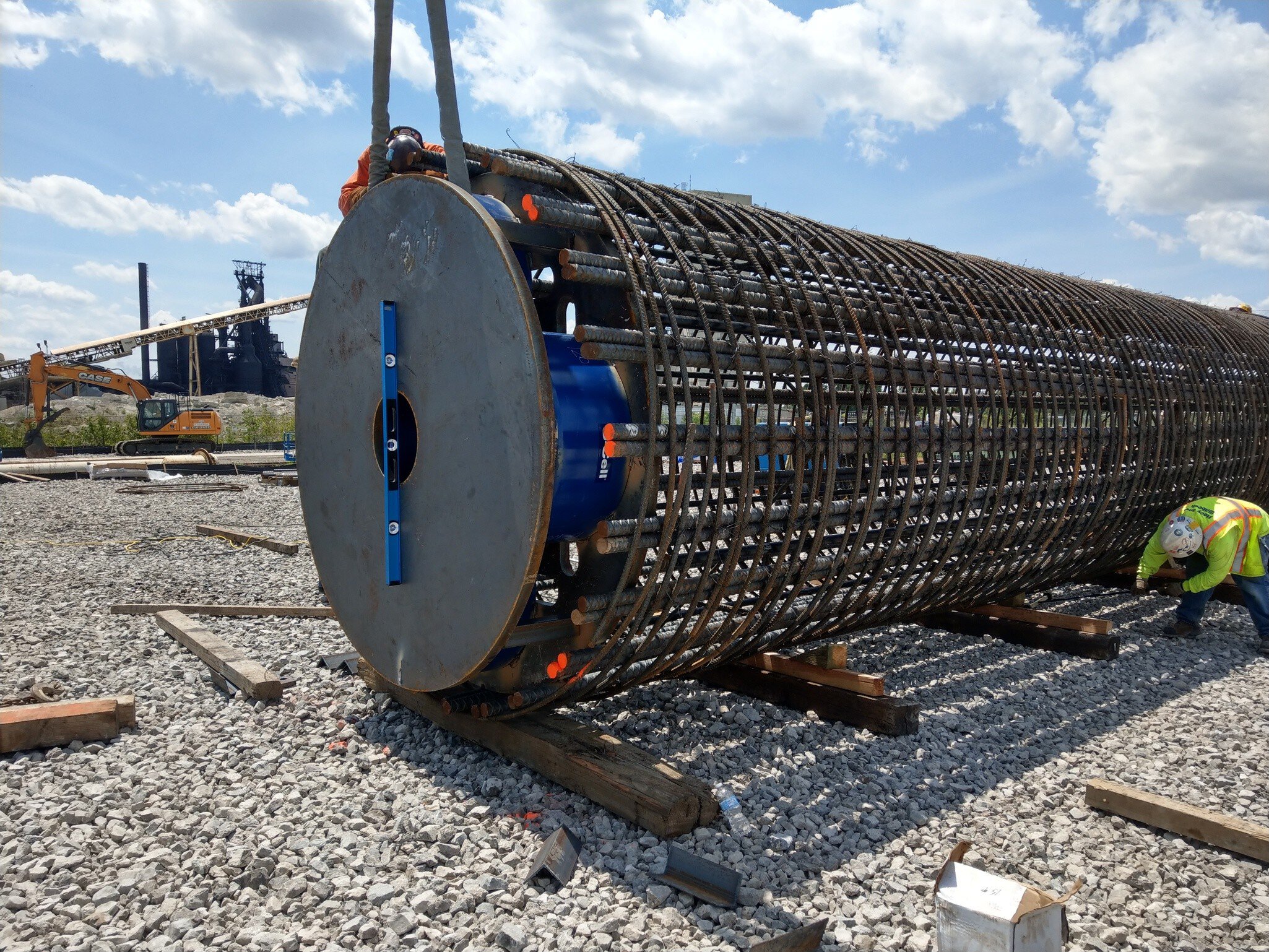
After the project award, and on our recommendation, the contractor performed two additional Osterberg Cell® tests to support the final design, which measured even higher foundation capacities than used during tender design. This approach enabled the designer to further optimise the length of the foundations, resulting in significant cost reductions and schedule efficiencies.
3. Construction observation
To ensure a high-quality foundation was built, we observed the construction of the deep-drilled shaft foundations and shallow marine footings, continually checking that the construction methods and procedures complied with the foundation specifications and design assumptions.

Used technology
Osterberg Cell® test

Osterberg Cell® (O-Cell®) test
The original Osterberg Cell® (O-Cell®), only offered by Fugro, significantly reduces construction costs with foundation design calibration. Internationally recognised, the O-Cell® is a leading bi-directional method for load testing drilled shafts and piles. Only O-Cell® has proprietary friction-free and tilt-tolerant design. It is the ideal solution for reliable design calibration.
Expected lifespan
Years
Innovative system
The marine environment and the high currents experienced, made inspecting the shallow footings excavation very challenging, so we worked closely with the contractor to develop a system for remotely approving foundation excavations in real-time.
This solution included two separate cleaning and inspection operations immediately before and after the pre-cast footing placement. For the latter, a gap of around 60 cm was maintained between the bottom of footing and the base of excavation, to allow divers to perform the final cleaning and inspection. The gap was then filled with concrete.
Our approach
Our approach prevented any schedule delays and ensured the client’s highly ambitious construction timelines were met. Our geotechnical design recommendations were based on combined advanced analysis and numerical modelling techniques (main tower foundations) and Osterberg Cell® tests to deliver a robust, yet optimal design.
Since its completion in June 2019, the Samuel De Champlain Bridge has kept traffic flowing at a rate of more than 59 million cars, buses and trucks each year, with an expected 125 years lifespan.
Key facts:
59 million vehicles cross Montreal’s Champlain Bridge each year
The Samuel De Champlain Bridge is just under 3.4 km long and comprises three independent superstructures:
- Asymmetric cable-stayed bridge signature span – 529 m long with a single 158.6 m tower supported on 1.2 m diameter drilled shaft groups
- West Approach – 2,044 m long, comprising 26 shallow marine footings on rock
- East Approach – 762 m long, comprising shallow foundations on rock and two groups of three shafts drilled in rockSubsurface conditions include up to 10 m of dense glacial till overlying Utica Shale rock

What we do at Fugro